







How transport limits affect skid-mounted sewage treatment plant design
A skid mounted sewage treatment plant can satisfy treatment calculations yet remain impractical to deliver if its dimensions, weight or lifting arrangement exceed the available transport route. Transport limits therefore belong in the design basis before tank geometry and equipment layout are fixed. They determine not only whether a module can reach the site, but also how much treatment volume it can contain and how much assembly must be completed after delivery.
The decisive constraint is the complete delivery chain: factory loading, inland haulage, port handling, sea freight where applicable, final access and placement on the foundation. A design that fits one shipping stage may fail at another. The lowest bridge, most restrictive turn, permissible axle load or available crane configuration can govern the module arrangement.
Define the transport envelope before fixing the process layout
There is no universal maximum size for a transportable sewage treatment skid. Road limits depend on jurisdiction, vehicle configuration and route, while abnormal-load permits introduce additional conditions rather than guaranteeing access. A route assessment should establish permitted overall dimensions, bridge restrictions, turning geometry, gradients and site entrance clearances.
The transport envelope must include the trailer and all projections. Overall road height is measured from the road surface, not from the skid base. Pipe vents, lifting lugs, handrails, electrical enclosures and packaging can turn an otherwise acceptable module into an over-height or over-width load.
For container shipment, internal dimensions alone are insufficient. Door openings, loading method, payload, floor loading and securing arrangements must also be checked against the selected container’s specifications. A module that fits inside geometrically may still be impossible to load through the doors or may impose unacceptable concentrated loads.
Tank geometry must preserve effective treatment capacity
Transport width and height directly constrain reactor cross-section. Reducing tank depth to pass beneath an obstruction does not simply produce a shorter version of the same process. It changes available liquid volume, aeration submergence, mixing conditions and potentially the geometry required for solids separation.
Consider an illustrative average flow of 120 m³/day and a selected hydraulic retention time of eight hours. The corresponding effective liquid volume is 40 m³. This is an arithmetic example, not a treatment design recommendation. If transport restrictions reduce the available internal cross-sectional area to 4 m², obtaining that volume requires 10 m of effective tank length—before allowing for partitions, freeboard, equipment displacement or other process compartments.
Lengthening a tank can recover volume, but it also changes flow distribution, structural bending and support requirements. Where width is constrained, a narrow settling compartment may lack sufficient surface area even when total tank volume appears adequate. Clarification cannot be validated by retention time alone.
Likewise, membrane and attached-growth processes do not remove dimensional constraints. Membrane modules require installation clearances, air distribution and withdrawal space. Media-based reactors require suitable mixing and retention screens. A compact process should be selected against influent characteristics, effluent requirements and operating capability—not used merely to justify fitting the plant onto one truck.
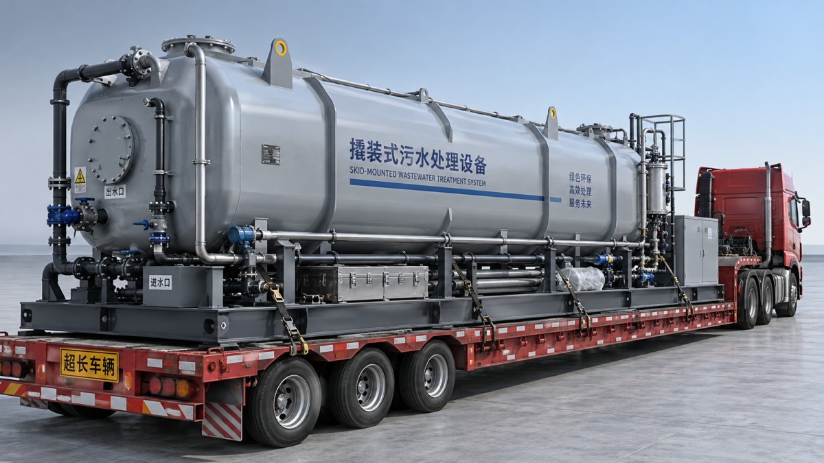
A useful layout drawing should distinguish the shipping envelope from the operating and maintenance envelopes. Removable handrails may solve a delivery problem; inadequate overhead clearance for membrane extraction or pump removal remains an operating problem.
Shipping weight is not operating weight
The mass schedule should separately identify dry equipment weight, shipping weight, operating weight and any hydrostatic test condition. Shipping weight includes packaging, temporary bracing, loose items secured to the skid and retained liquids. Operating weight includes process water, media, sludge inventories and chemical stocks where relevant.
Water weighs approximately one tonne per cubic metre. Even a small undrained compartment can materially alter lifting loads and axle reactions. The transport specification should therefore define the required drain-down condition and provide accessible drain points rather than simply describing the unit as “shipped empty.”
For a tall or unevenly loaded skid, total mass alone is an inadequate check. A blower package or electrical enclosure at one end can shift the centre of gravity sufficiently to affect trailer axle loading and lifting balance. The supplier should provide centre-of-gravity coordinates for the actual shipping configuration, including components removed or relocated for transport.
Road transport, lifting and operation impose different structural load cases. A tank designed for hydrostatic pressure still needs verification for transport acceleration, restraint forces and lifting-induced distortion. Temporary supports or bracing may be required, with their removal clearly identified in installation instructions.
Module splits create hydraulic and control interfaces
Dividing a plant into smaller modules can avoid exceptional transport requirements, but each split creates field connections and commissioning obligations. Suitable boundaries should follow process and mechanical logic, not simply equal module lengths.
A gravity connection between biological treatment and clarification is particularly sensitive to installed elevations. Available hydraulic head must accommodate pipe friction, fittings, entrance and exit losses, and downstream operating levels. A connecting pipe that appears adequate in diameter can still cause upstream flooding if foundation levels or nozzle elevations are wrong.
Pumped transfers offer more flexibility in elevation, but introduce pumps, controls, energy consumption and potential changes to process behaviour. Where settled solids are present, transfer arrangements must also avoid deposition and blockage.
Interface drawings should specify more than flange size. They should define nozzle coordinates, connection orientation, gasket and bolt requirements, cable terminations, instrument responsibilities and allowable installation tolerances. Separate air headers need a balancing arrangement; separate process tanks need a coordinated level-control philosophy.
Interconnecting pipework should not be forced into alignment to compensate for foundation errors. Doing so can load tank nozzles, disturb seals and transmit stresses into equipment. Defined support locations and an engineered allowance for installation adjustment are preferable to relying on unplanned field modification.
Lifting and site access can outweigh freight savings
Crane selection depends on lift radius, boom configuration, rigging and ground conditions—not just the crane’s nominal capacity. A module that can be lifted beside the delivery vehicle may exceed available capacity when placed beyond a building or across an excavation.
Lifting lugs, spreader arrangements and sling angles must be engineered for the specified lift. Shallow sling angles increase sling tension and can introduce substantial horizontal forces. Tank walls and roof members should not be assumed to tolerate these loads without verification.
The installation sequence also needs a physical access check. The first module placed must not block trailer access or crane positioning for the next. Adequate space is required to connect flanges, install removed components and inspect joints. Splitting one large package into several smaller units is only beneficial if those interfaces remain accessible after placement.
Require evidence that covers every delivery condition
No single certificate establishes transport suitability. Where applicable, the IMO/ILO/UNECE Code of Practice for Packing of Cargo Transport Units provides guidance on packing and securing cargo, but it does not replace route permits, structural calculations or a lift plan. Similarly, an ISO freight container’s approval does not automatically validate equipment installed inside it. Modified containers require assessment of the effects on their structure and applicable approvals.
A technically credible submission should connect the process design to the logistics assumptions through identifiable documents:
- General arrangement drawings showing shipping dimensions, operating access and removable components.
- A mass schedule and centre-of-gravity information for each shipping unit.
- Transport restraint and lifting details supported by appropriate engineering checks.
- Module interface drawings linked to foundation elevations and the hydraulic profile.
- A factory testing and site acceptance plan identifying what must be repeated after reassembly.
Factory testing cannot verify every site-installed connection. Field joints need appropriate leak testing, electrical reconnections need inspection and functional checks, and controls must be tested across module boundaries. Treatment acceptance must remain separate from mechanical completion because biological performance depends on operating conditions and process establishment.
The sound design is not necessarily the one with the fewest modules. It is the arrangement that preserves required process volume and hydraulic behaviour while remaining deliverable, liftable and maintainable. Those conditions should be demonstrated before fabrication, when changing a module boundary is still a design decision rather than a site repair.



 Is a skid-mounted sewage treatment plant suitable for repeated relocation?
 How to restart a skid-mounted sewage treatment plant after storage
 How transport limits affect skid-mounted sewage treatment plant design
 What site preparation does a skid-mounted sewage treatment plant need?
 How to verify a modular sewage treatment plant's effluent quality
 Can a modular sewage treatment plant expand without a shutdown?
GET A FREE QUOTE
Service Commitment: Upon receipt of your message, a dedicated representative will contact you as soon as possible to provide efficient and professional service support.
